
Driven pile (typical CA / Chile 1P SAT)
W6×9 H-pile · 1.50 m reveal · 2.5 m embedment · ~4.0 m total. Steel left in the ground.
Proof
Stow that unloads the drive. Mass on grade that does not scour, sink, or take a residual set like a pile.

Third party
RWDI — wind tunnel, ASCE 7

Third party
Black & Veatch — independent engineering assessment

Third party
Kiwa PVEL — one-year outdoor study, bifacial gain on reflective foundation
Dual-glass optimized
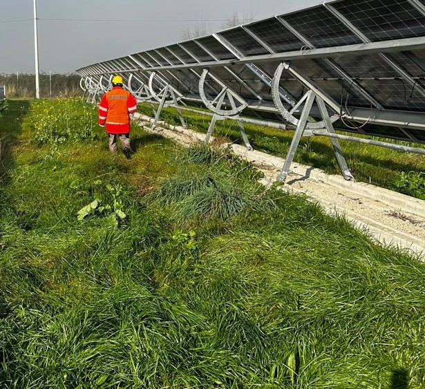
A torque-tube SAT hangs large-format dual-glass from one pipe. Unsupported span plus thermal expansion puts a fishbone in the glass. Cracks may follow on the backsheet.
StormTracker carries the modules on two purlins across a geared cross-beam — 1.112 m box, 0.636 m overhang. At the same 47 m•s face pressure the glass moment is 0.21 kN·m/m, 43% of the single-pipe hang. Dual-glass can be thin-framed because the tracker is not asking the glass to be a beam.
Face pressure p = 976 Pa × 0.714 = 697 Pa · 47 m•s · StormLock 0°2.3× — StormTracker glass moment is 43% of the single-pipe hang (0.21 vs 0.50 kN·m/m).
Torque-tube SAT
Single pipe + clamps. Two 1.192 m cantilevers. Glass M ≈ 0.50 kN·m/m at 47 m•s.
Purlins on geared cross-beam
Two purlins at 1.112 m. Overhang 0.636 m each side. Glass M ≈ 0.21 kN·m/m at 47 m•s.
Unit-strip east–west bend at the same face pressure. Not a PE glass-stress seal.
700 Wp class · 2.384 × 1.303 m dual-glass. The tracker must not make the glass a beam.
Indigenous tribal site — buried archaeological resources
Stow
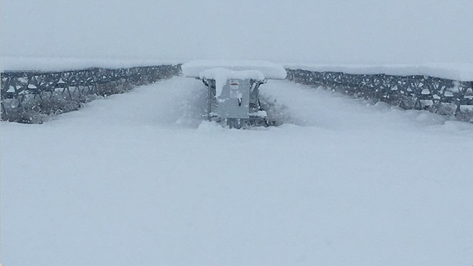
In stow the drive tube fully disengages from the row loads. It is a mechanical disconnect, not a parked gear sitting under snow.
A surprise snow dump has no path into a locked torque tube. There is nothing for that load to wind, and nothing to take a permanent set. Typical torque-tube SATs do not have that out.
120 modules · one drive · 3″ slew
Ancient lakebed — corrosive active clays
Inundation
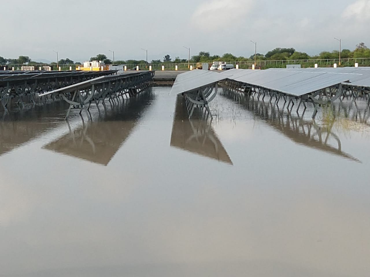
The foundation is in the water. That is the point. Distributed mass on the surface — not a stick driven into the bed.
A single pile concentrates load into one point. Flow nucleates there and scours the soil away. A mass foundation has no point to attack. Inundation is a site condition. It is not a failure mode.
Bearing
A driven pile puts a 6-module table on 0.02 m² of steel. That is a point. Soft clay, fill, and a high water table punch through it. Split Rail and Full Reflector put the same table on mass on grade.
| Foundation | Plan bearing | vs pile | Contact |
|---|---|---|---|
Driven steel pile 3 m W8×10 · one pier · boxed H 7.89″ × 3.94″ | 0.02 m² | — | |
Split Rail Foundation Two slipform rails · A-frame resists overturn · 0 piles | 3.68 m² | ~180× | |
Full Reflector Foundation Continuous ballast on grade · albedo + mass | 9.10 m² | ~450× |
Plan area on grade per 6-module table · 700 Wp · 35 m•s. Sinking is bearing, not pile skin. W8×10 plan = 0.020 m² (AISC d × bf). One pier per table.
Skin
Shaft resistance is unit skin × perimeter × embedment. Unit skin is the site. The area is the pile.
Even the skin — 1.8 to 2.3 m² — is less contact than Split Rail (3.68 m²) and far less than Full Reflector (9.10 m²), and it is buried, not on grade. Sinking is the 0.02 m² point.
Seismic
A driven pile is socketed in the ground. After a strong event the shaft can yield or the soil can liquefy. That displacement stays. Re-level means pulling steel out of the hole, or living with a bent row.
Split Rail is a continuous slipform foundation on grade — 0 piles. There is no embedment to take a permanent set. Flex-coupled tables can slip at the joint and be re-leveled. The dashed line is serviceability. The solid line is residual embedment: approximately zero.
Pin 1.50 m AGL · 700 Wp bifacial dual-glass · 0 piles
Pile yield / liquefaction set
Felt intensity at the plant — not Richter magnitude. A distant M7 can shake less than a nearby M5.
| PGA | US (Modified Mercalli) | Japan (JMA 震度) | Recorded example |
|---|---|---|---|
| 0.2 g | VII — strong, standing is hard | 5強 | Loma Prieta 1989, Emeryville 0.23 g · Tōhoku 2011 in Tokyo |
| 0.4 g | VIII — ordinary buildings damaged | 6弱 | Imperial Valley 1979, El Centro 0.39 g · Ōsaka northern 2018 |
| 0.6 g | VIII–IX — very destructive | 6強 | Northridge 1994, Rinaldi 0.63 g · Kobe 1995 ~0.8 g |
PGA is the station, not the earthquake. A valley over, the same event is a different number. PEER / JMA records.
Driven pile (typical CA / Chile 1P SAT)
W6×9 H-pile · 1.50 m reveal · 2.5 m embedment · ~4.0 m total. Steel left in the ground.
Split Rail Foundation (47 m•s | 105 mph)
Continuous slipform ballast · pin 1.50 m AGL · 0 driven piles. Flex-coupled tables — joint slip only.
Next